- Description
 
                                - Specifications
 
                                - Customize
 
                                - Downloads
 
                                
                                - Ask a Question


	Introductions: 
	M860C stepper drives adopting Leadshine latest advanced stepper control technology. Those stepper drives are highly reliable with good performance and highly competitive cost. M860C stepper drives feature advanced DSP microstepping and anti-resonance technology for optimized torque, smooth motion, extra low noise, and very low motor heating. The feature of stepper motor auto identification & configuration will allow the driven stepper motors always running at the optimized performance. 
	M860C stepper drives are easy to configure and setup. Output current and micro step resolution can be simply set up via DIP switch configuration. 
	M860C stepper drives are ideal for step & direction applications requiring step & direction 2 or 4 phase stepper motor control.   
	Features:  
	Step & direction or CW/CCW Control 
	Smooth motion, low motor heating, extra low noise & vibration 
	High reliability and extra low failure rate 
	Anti-resonance 
	Automatic stepper identification and configuration 
	Easy DIP switch configuration & simple setup 
	Idle current reduction 
	Electrical Specifications: 
	
		
			| 
				  
			 | 
			
				 
					Min. 
				 
			 | 
			
				 
					Typical 
				 
			 | 
			
				 
					Max. 
				 
			 | 
			
				 
					Unit 
				 
			 | 
		
		
			| 
				Input Voltage 
			 | 
			
				 
					20 
				 
			 | 
			
				 
					68 
				 
			 | 
			
				 
					80 
				 
			 | 
			
				 
					VDC 
				 
			 | 
		
		
			| 
				Output Current (Peak) 
			 | 
			
				 
					2.4 
				 
			 | 
			
				 
					- 
				 
			 | 
			
				 
					7.2 
				 
			 | 
			
				 
					A 
				 
			 | 
		
		
			| 
				Logic Signal Voltage 
			 | 
			
				 
					- 
				 
			 | 
			
				 
					5 
				 
			 | 
			
				 
					- 
				 
			 | 
			
				 
					VDC 
				 
			 | 
		
		
			| 
				Logic Signal Current 
			 | 
			
				 
					7 
				 
			 | 
			
				 
					- 
				 
			 | 
			
				 
					16 
				 
			 | 
			
				 
					A 
				 
			 | 
		
		
			| 
				Pulse Input Frequency 
			 | 
			
				 
					- 
				 
			 | 
			
				 
					- 
				 
			 | 
			
				 
					200 
				 
			 | 
			
				 
					kHz 
				 
			 | 
		
		
			| 
				Over Voltage Protection 
			 | 
			
				 
					- 
				 
			 | 
			
				 
					35 
				 
			 | 
			
				 
					- 
				 
			 | 
			
				 
					VDC 
				 
			 | 


	 Tags:Digital ,Stepper, Driver, Stepper, Driver, for, Nema, 24, 34, Stepper, Driver, M860C 


	Typical Configuration 


	Connector Specifications 
	 
	(1)  LED indicators 
There are two LED indicators, one green and one red. Here are their definitions 


			| 
				 
					LED Light Color 
				 
			 | 
			
				 
					Function 
				 
			 | 
			
				 
					Description 
				 
			 | 
		
		
			| 
				 
					Green 
				 
			 | 
			
				 
					Power Indicator 
				 
			 | 
			
				 
					Solid green when powered on. 
				 
			 | 
		
		
			| 
				 
					Red 
				 
			 | 
			
				 
					Fault Indicator 
				 
			 | 
			
				 
					No light when normal. 
				 
				
					Blinks periodically in every 3 seconds when. 
				 
				
					─ “Over Current protection”: blind one time periodically every 3 seconds 
				 
				
					─ “Over Voltage protection”: blind one time periodically every 3 seconds 


			 | 


	Control Signal Connections


				| 
					 
						Pin 
					 
				 | 
				
					 
						Description 
					 
				 | 
				
					 
						Remark 
					 
				 | 
			
			
				| 
					 
						PUL+ 
					 
				 | 
				
					 
						Pulse + input  
					 
				 | 
				
					 
						5V pulse signal. A resistor is needed to
  12 V or 24V signal 
					 
				 | 
			
			
				| 
					 
						PUL- 
					 
				 | 
				
					 
						Pulse - input 
					 
				 | 
			
			
				| 
					 
						DIR+ 
					 
				 | 
				
					 
						Direction + input 
					 
				 | 
				
					 
						5V direction signal. A resistor is needed
  to 12 V or 24V signal 
					 
				 | 
			
			
				| 
					 
						DIR- 
					 
				 | 
				
					 
						Direction + input 
					 
				 | 
			
			
				| 
					 
						ENA+ 
					 
				 | 
				
					 
						Enable+ Input 
					 
				 | 
				
					 
						A 5V enable signal can be used to clear
  “Over Voltage” protection 
					 
				 | 


	(1)    DIP Switch Settings 


				| 
					 
						Model 
					 
				 | 
				
					 
						SW1-SW3 
					 
				 | 
				
					 
						SW4 
					 
				 | 
				
					 
						SW5-SW6 
					 
				 | 
				
					 
						SW7-SW8 
					 
				 | 
			
			
				| 
					 
						M860C / MA860C 
					 
				 | 
				
					 
						for output current
  settings 
					 
				 | 
				
					 
						for idle current
  settings 
					 
				 | 
				
					 
						for micro step settings 
					 
				 | 


	(1)    Motor Connections 


			| 
				 
					A+ 
				 
			 | 
			
				 
					Connect to A+ wire of the driven stepper
  motor 
				 
			 | 
		
		
			| 
				 
					A- 
				 
			 | 
			
				 
					Connect to A- wire of the driven stepper
  motor 
				 
			 | 
		
		
			| 
				 
					B+ 
				 
			 | 
			
				 
					Connect to B+ wire of the driven stepper
  motor 
				 
			 | 
		
		
			| 
				 
					B- 
				 
			 | 
			
				 
					Connect to B- wire of the driven stepper
  motor 
				 
			 | 


	Typical Connection Diagrams


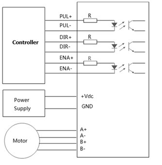
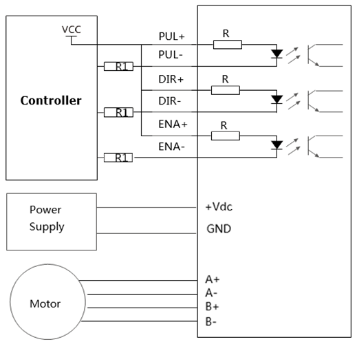
	                          (Typical)                                                               (Common Anode)     
	
 
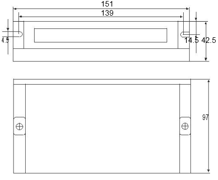
	Mechanical Specifications (unit: mm    1 inch = 25.4 mm) 
	